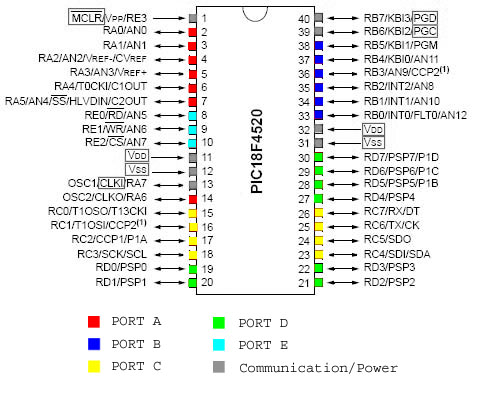
- At89c52 Microcontroller Pin Diagram Circuit
- At89c52 Microcontroller Pin Diagram Unlabeled
- At89c52 Microcontroller Pin Diagram Types
- At89s52 Microcontroller Pin Description
- At89c52 Microcontroller Pin Diagram Connector
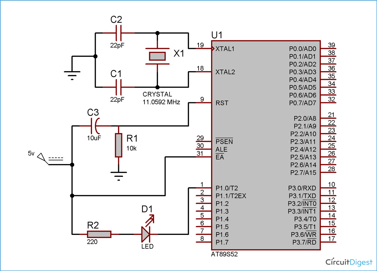
- At89s52 Microcontroller Circuit Diagram
A high density nonvolatile memory highly advanced technology is used to manufacture devices and industry standard MCS-51 instruction set and pin diagram. Datasheet 8051 Microcontroller Family Variants AT89C1051, AT89C2051, AT89C4051, AT89C51, AT89C52, AT89C53, AT89C55, AT89S51, AT89S52, AT89S53, AT89S8252. 8-Bit Microcontroller with 8K Bytes Flash, AT89C52 datasheet, AT89C52 circuit, AT89C52 data sheet: ATMEL, alldatasheet, datasheet, Datasheet search site for Electronic Components and Semiconductors, integrated circuits, diodes, triacs, and other semiconductors. AT89C52 microcontroller Pin Diagram and Pin Functions – Free Microcontroller projects Unknown September 5, at 9: Atmel Studio 6 free http: Mircocontroller who viewed this item also viewed. Resume making your offer if the page doesn't update immediately.
View and Download Atmel AT89C52 manual online. 8-Bit Microcontroller with 8 Kbytes Flash. AT89C52 Microcontrollers pdf manual download. = 0 '1' '0' RCLK CLOCK CONTROL ÷ C/T2 = 1 '1' '0' T2 PIN TCLK RCAP2H RCAP2L CLOCK TRANSITION ÷ DETECTOR TIMER 2 T2EX PIN EXF2 INTERRUPT CONTROL EXEN2 AT89C52. This is the circuit diagram of the digital clock using 8051 microcontroller. As we can see the microcontroller is connected to three 7 segment display with distinct ports not multiplexed and the last hour digit is only connected to a pin as it only shows 1. LED and buzzer are self explanatory according to the code.
Different temperature indicator project with discrete component is already published in www.electronicsproject.org. Now, here is a microcontroller based temperature indicator with LCD for better and precise reading. A temperature sensor DS1621 is used here for better result. As we know that programming language 'C' is less complicated with well-defined syntax in compare to Assembly language so we write program for microcontroller in 'C'.
Circuit description
The circuit of temperature indicator is designed around microcontroller AT89C52 where DS1621 is used as temperature sensor. The block diagram of temperature indicator using AT89C52 is shown in figure 1.
The temperature sensor IC3 is used to sense temperature and read as 9-bit value. The pin 1 and 2 of sensor (IC3) is connected to pin 11 and 10 respectively of microcontroller (IC2) as shown in circuit diagram. The sensor (IC3) activates its thermal alarm output in exceeding of user-defined high temperature until temperature drop below user-defined low temperature. Non-volatile memory is used to store user-defined temperature.
A crystal oscillator XTAL1 is connected to XTAL pin of microcontroller (i.e. pin 18 and 19) for operating of microcontroller. A high pulse on RST pin (pin 9) through capacitor C5 is given while the oscillator is running for reset the microcontroller. Pin 31 is also connected to +Ve supply for execution of internal program. During flash programming at 12V programming is selected pin 31 is also used to receive 12V programming enable voltage.
The 16*1 LCD is used as display where VR1 is used to control the intensity of display. The connection of LCD is given in table 2 where pin 15 and 16 is not used.
Software:- A cross-complier C51 version 7.10 from keil software is used here for compiling the program code written in C.
TABLE 1DS1621 Command SetInstructionDescriptionProtocolRead TemperatureReads last converted temperature value from temperature register.
AahRead CounterReads value of count remaining from counter.
At89c52 Microcontroller Pin Diagram Circuit

Reads value of slope accumulator.
A9hStart Convert TIndicates temperature conversion.
EEhStop Convert THalts temperature conversion.
22hAccess THReads or writes low temperature limit value into TH register.
A1hAccess TLReads or writes low temperature limit value into TL register.
A2hAccess ConfigurationReads or writes configuration data to configuration register.
AchTABLE 2Pin Connection of the LCDPin No.FunctionsPin 1Ground (Gnd)At89c52 Microcontroller Pin Diagram Unlabeled
Pin 2+Vcc
PARTS LIST
Resistors (all ¼-watt, ± 5% Carbon)
RAt89c52 Microcontroller Pin Diagram Types
1 = 1 KΩR2 = 47 KΩR3 = 10 KΩR4, R5 = 4.7 KΩVR1 = 1 KΩ (Preset)Capacitors
C1 = 470 µF/25V (Electrolytic)C2 – C4 = 0.1 µF (Ceramic)C5 = 10 µF/16V (Electrolytic)C6, C7 = 33 pF (Ceramic)Semiconductors
IC1 = LM7805 (Voltage Regulator)IC2 = AT89C52 (Microcontroller)IC3 = DS1621 (Temperature Sensor)D1 – D4 = 1N4007 (Rectifier Diode)LED1 = RED12 thoughts on 'Temperature Indicator Using AT89C52'
This Project will show you how to Burn Hex File For Atmel Microcontroller using Arduino Uno.
- 18,679 views
- 4 comments
- 22 respects
Components and supplies
Necessary tools and machines
|
Apps and online services
About this project
In this Tutorial I will show you how to Burn Your Hex File To AT89c52 using Arduino Uno in just few easy steps. For this we have to interface AT89c52 to Arduino Uno and give it led indications via interfacing LED to At89c52.
Step 1: Bill Of Materials
- Arduino UNO

- AT89C52 Microcontroller
- 10uF Capacitor

- Jumper Wires
- 8.2kohm Resistor
- 510 ohm Capacitor
- LED
- 12 MHz Crystal
- 2 x 33pF Capacitor
At89s52 Microcontroller Pin Description
Step 2: Connecting Microcontroller
Connect the micro controller as mentioned below:
- At89c52 Arduino Uno
- Pin 6 Pin 5
- Pin 7 Pin 4
- Pin 8 Pin 3
At89c52 Microcontroller Pin Diagram Connector
- Pin 9 Pin 2
Step 3: Crystal
Connect a Crystal across Pin 18 and 19 of Atmel and then connect two 33pf capacitors from pin 18 and 19 to Ground of Atmel. See Schematics Section For Full Circuit Diagram.
Step 4: VCC And GND
Connect 5v Pin of Arduino Uno to 40th pin of Atmel and GND pin to 20th Pin of Atmel.
Step 5: Interfacing LED
Interface LED with the help of Circuit Diagram provided in Schematics Section.
Step 6: Software
We need 8051 SPI Programmer to Burn Hex File To 89c52. The Link is Provided in Software Section. Dr stika plus windows 7. Upload Code provided to Arduino UNO and your Programmer is ready.
Code

Reads value of slope accumulator.
A9hStart Convert TIndicates temperature conversion.
EEhStop Convert THalts temperature conversion.
22hAccess THReads or writes low temperature limit value into TH register.
A1hAccess TLReads or writes low temperature limit value into TL register.
A2hAccess ConfigurationReads or writes configuration data to configuration register.
AchTABLE 2Pin Connection of the LCDPin No.FunctionsPin 1Ground (Gnd)At89c52 Microcontroller Pin Diagram Unlabeled
Pin 2+VccPin 3V0 (display intensity control)Pin 4RS (connected to pin P3.2 of AT89C52)Pin 5R/W (connected to pin P3.3 of AT89C52)Pin 6EN (connected to pin P3.4 of AT89C52)Pin 7D0 (connected to pin P1.0 of AT89C52)Pin 8D1 (connected to pin P1.1 of AT89C52)Pin 9D2 (connected to pin P1.1 of AT89C52)Pin 10D3 (connected to pin P1.3 of AT89C52)Pin 11D4 (connected to pin P1.4 of AT89C52)Pin 12D5 (connected to pin P1.5 of AT89C52)Pin 13D6 (connected to pin P1.6 of AT89C52)Pin 14D7 (connected to pin P31.7 of AT89C52)Pin 15Backlight +Vcc (not used)Pin 16Backlight Gnd (not used)PARTS LIST
Resistors (all ¼-watt, ± 5% Carbon)
RAt89c52 Microcontroller Pin Diagram Types
1 = 1 KΩR2 = 47 KΩR3 = 10 KΩR4, R5 = 4.7 KΩVR1 = 1 KΩ (Preset)Capacitors
C1 = 470 µF/25V (Electrolytic)C2 – C4 = 0.1 µF (Ceramic)C5 = 10 µF/16V (Electrolytic)C6, C7 = 33 pF (Ceramic)Semiconductors
IC1 = LM7805 (Voltage Regulator)IC2 = AT89C52 (Microcontroller)IC3 = DS1621 (Temperature Sensor)D1 – D4 = 1N4007 (Rectifier Diode)LED1 = RED12 thoughts on 'Temperature Indicator Using AT89C52'
This Project will show you how to Burn Hex File For Atmel Microcontroller using Arduino Uno.
- 18,679 views
- 4 comments
- 22 respects
Components and supplies
Necessary tools and machines
|
Apps and online services
About this project
In this Tutorial I will show you how to Burn Your Hex File To AT89c52 using Arduino Uno in just few easy steps. For this we have to interface AT89c52 to Arduino Uno and give it led indications via interfacing LED to At89c52.
Step 1: Bill Of Materials
- Arduino UNO
- AT89C52 Microcontroller
- 10uF Capacitor
- Jumper Wires
- 8.2kohm Resistor
- 510 ohm Capacitor
- LED
- 12 MHz Crystal
- 2 x 33pF Capacitor
At89s52 Microcontroller Pin Description
Step 2: Connecting Microcontroller
Connect the micro controller as mentioned below:
- At89c52 Arduino Uno
- Pin 6 Pin 5
- Pin 7 Pin 4
- Pin 8 Pin 3
At89c52 Microcontroller Pin Diagram Connector
- Pin 9 Pin 2
Step 3: Crystal
Connect a Crystal across Pin 18 and 19 of Atmel and then connect two 33pf capacitors from pin 18 and 19 to Ground of Atmel. See Schematics Section For Full Circuit Diagram.
Step 4: VCC And GND
Connect 5v Pin of Arduino Uno to 40th pin of Atmel and GND pin to 20th Pin of Atmel.
Step 5: Interfacing LED
Interface LED with the help of Circuit Diagram provided in Schematics Section.
Step 6: Software
We need 8051 SPI Programmer to Burn Hex File To 89c52. The Link is Provided in Software Section. Dr stika plus windows 7. Upload Code provided to Arduino UNO and your Programmer is ready.
Code
Schematics
Author
Patel Darshil- 24 projects
- 106 followers
Published on
August 27, 2017At89s52 Microcontroller Circuit Diagram
Members who respect this project
and 14 others
Don't miss out on this golden ticket to your American dream. H2Rush for Gold: California features - Over 40 Unique Locations that you can explore; - Two Game modes, challeging mode and the relax mode; - Comical characters and exciting gameplays; - Rush for Gold: California is a free full version game to download and play. California gold rush game full version free download for pc windows.
See similar projectsyou might like
